Following the previous article ComfyUI Batch Processing (Part 1): How to Implement Automatic Multi-Prompt Image Generation?, today we will seriously discuss the For Loop.
The For Loop node is actually quite abstract, and many who can use it still can’t explain it clearly.
Fortunately, the abstraction isn’t about the programming concept of a For loop—the programming concept of a For loop is simply a loop with a set number of iterations—but rather how to understand the operational logic of this node.
As long as you figure out what each connection point on the node represents, how inputs work, how outputs work, and how the looping occurs, it’s not hard to understand.
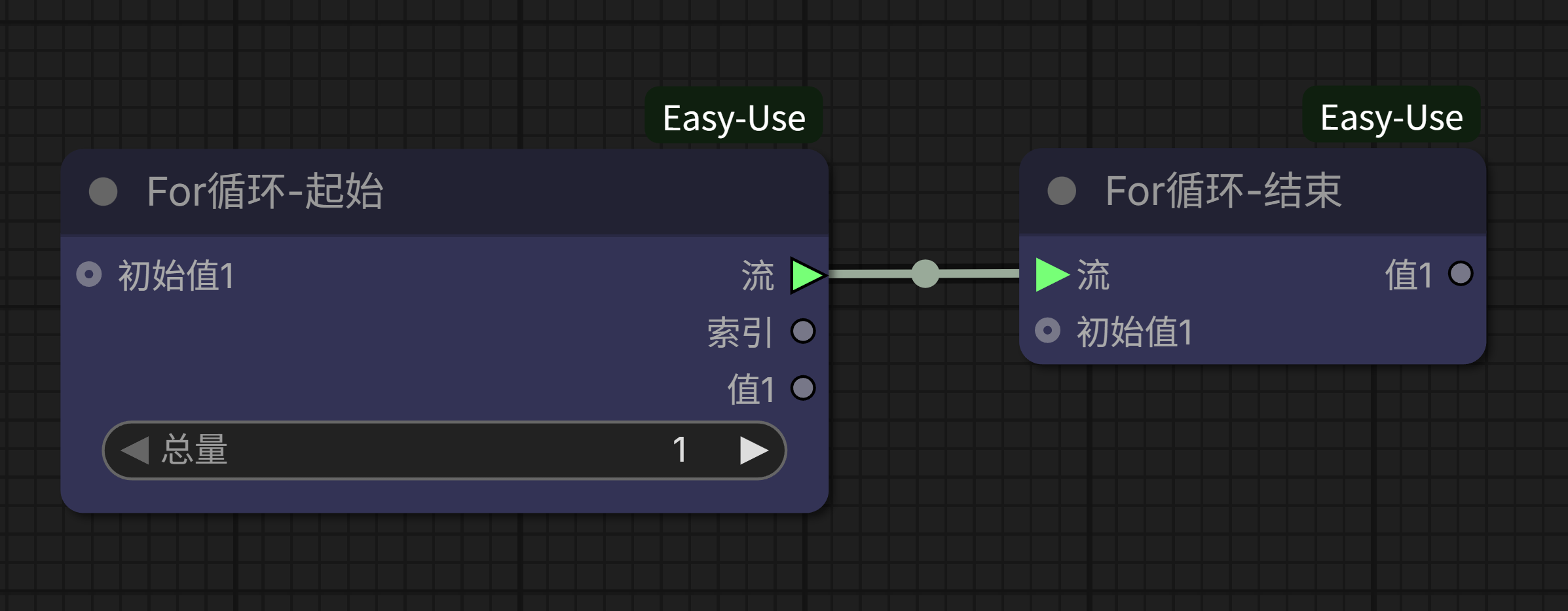
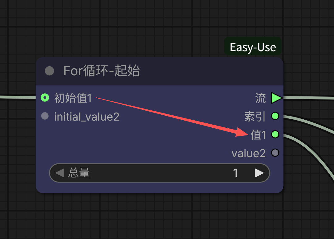
A friend told me that when explaining the For loop to others, he first connects it like the image below to form the simplest loop, then tries his best to use various vivid metaphors—conveyor belts, throwing sandbags… but no matter how concrete the metaphor, even he finds it abstract, and the listeners may not fully grasp it.
I think if you truly want to make it easy to understand, you still need to use the “clumsy” method: break it down, explain each connection point clearly, and the entire loop will naturally be explained.
[The following content is quite detailed; feel free to skip ahead]
First, you must understand one question: How is a loop considered formed?
The answer is very simple: A loop is formed when a circle is enclosed between the loop start node and the loop end node.
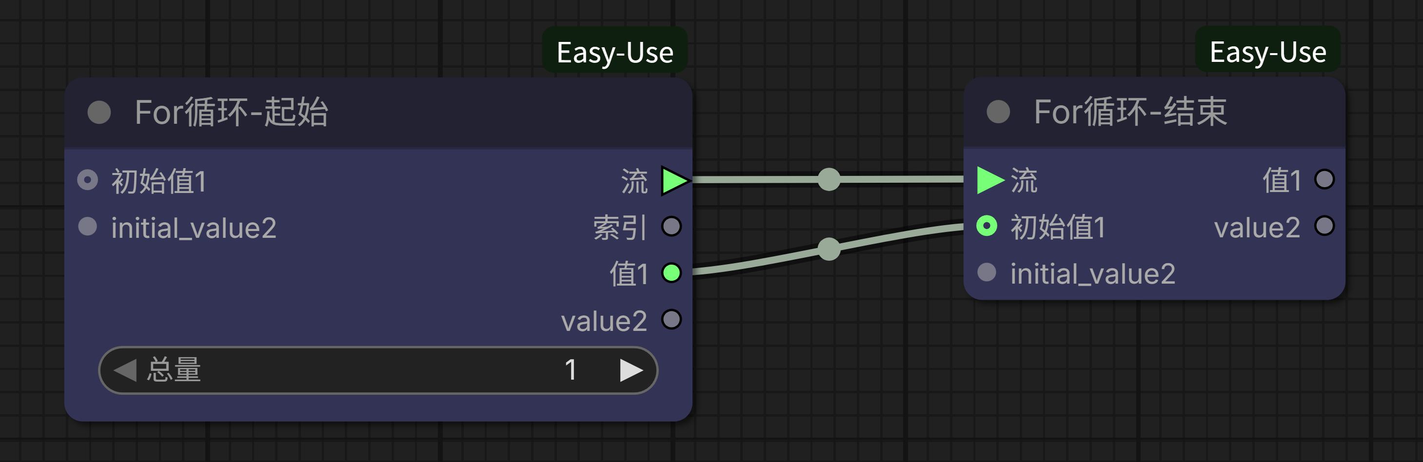
Whether it’s like the screenshot above, connecting from the start node’s value to the end node to close the loop:
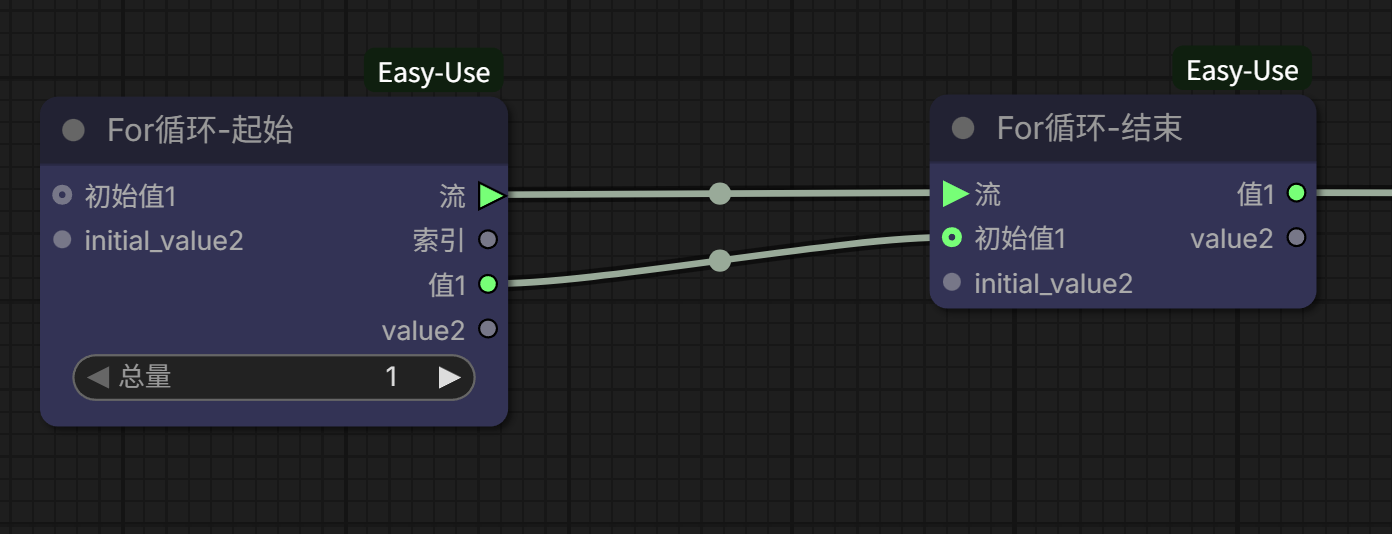
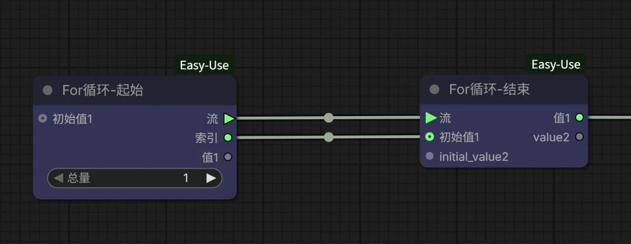
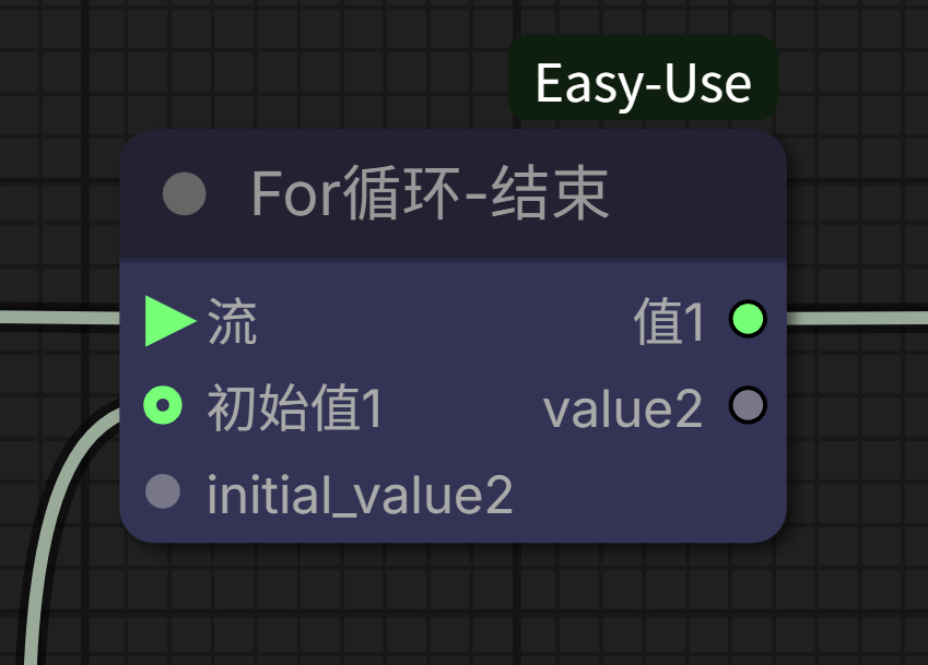
Or connecting from the start node’s index to the end node to close the loop:
With a loop circle, a loop can be formed.
Of course, this simplest loop has no effective content connected between the start and end points; it’s just spinning in circles, with no practical application meaning. However, the things we must first clarify are already established.
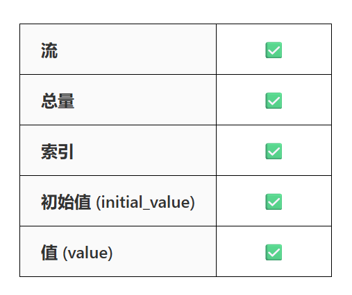
There are actually only 5 items, and two of them don’t need much explanation.
Flow: The flow output from the start node must be connected to the flow input of the end node to form a loop;
Total: This is the number of times the loop needs to run; the loop runs as many times as the number entered.
So now only 3 items remain:
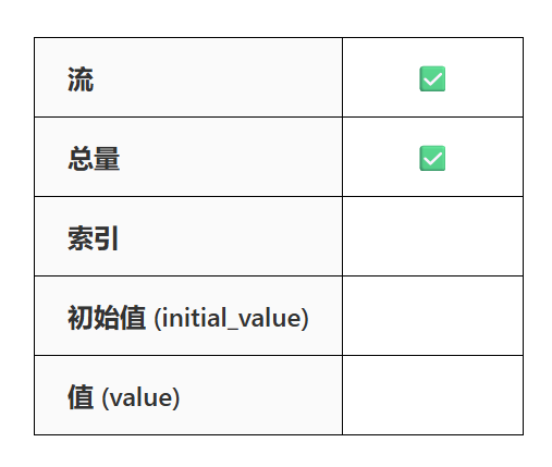
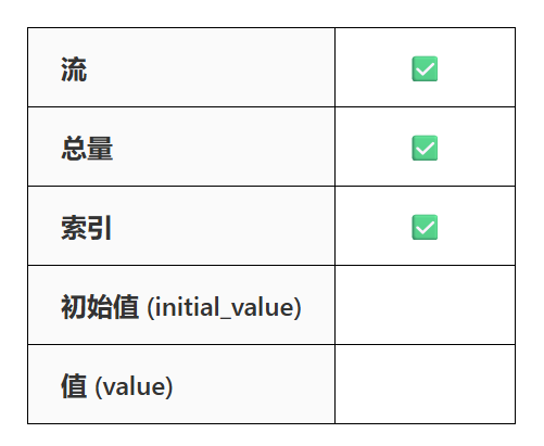
(The node’s translation is a bit incomplete; initial_value=initial value, value=value. Don’t be fooled by the Chinese and English; they actually mean the same thing. When the initial_value1/value1 connection point is used, the node will automatically display initial_value2/value2. For now, we won’t use initial_value2 and value2. Before we do, whenever I mention “initial value” below, it refers to “initial value1” by default, and “value” refers to “value1” by default.)
Before we formally begin, let me introduce two nodes:
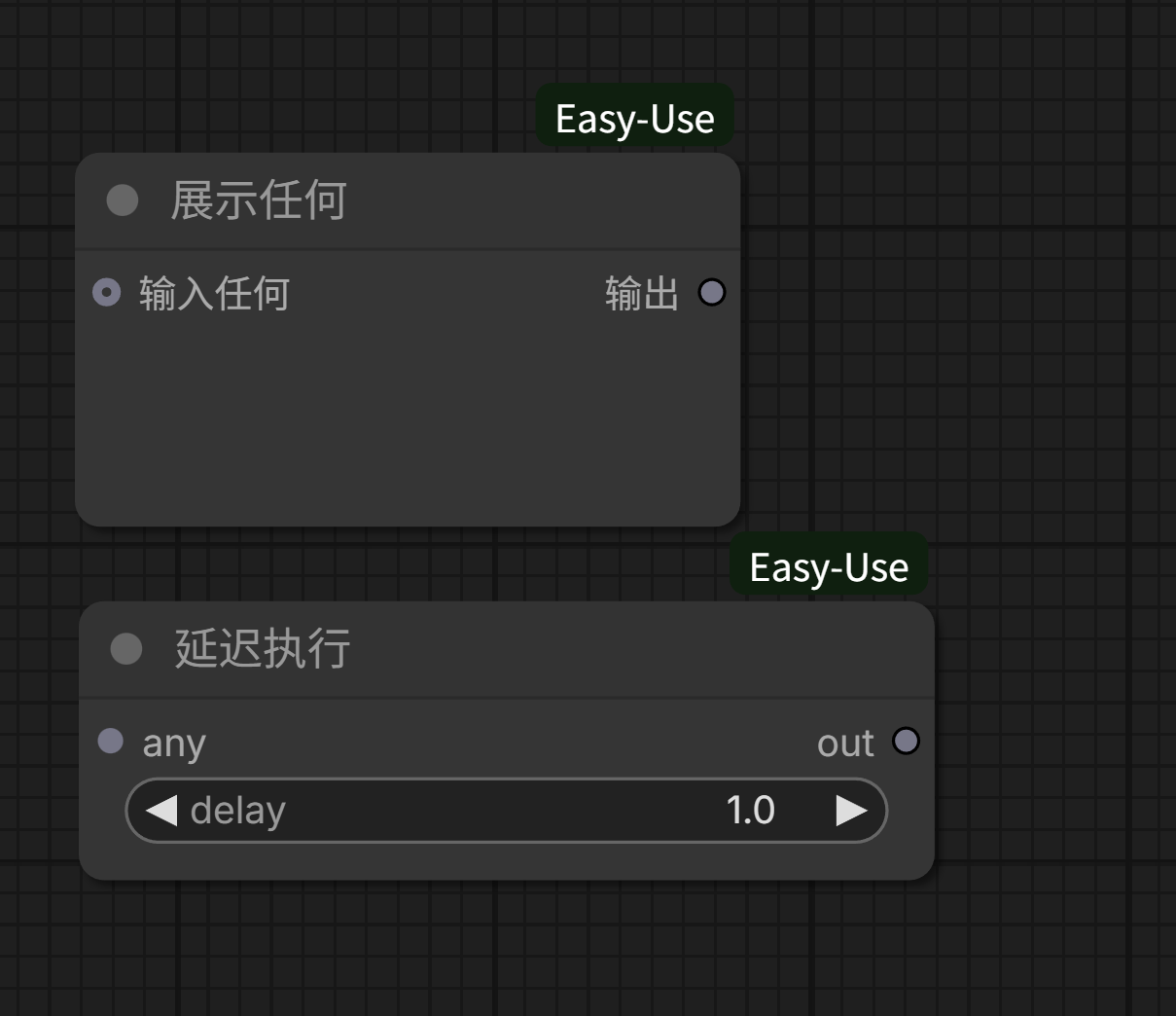
One is called “Show Any,” which can display the input and then output it as-is; the other is called “Delay Execution,” which pauses for a specified number of seconds when execution reaches this node before continuing.
These two nodes are very useful for learning unfamiliar workflows. They both input and output as-is. Besides providing display/delay functions, you can consider them equivalent to connection lines and just treat them as if they don’t exist.
Let’s first build a workflow that connects from the value to the end node. Then, we’ll add three “Show Any” nodes to observe the contents of the index, value, and initial value, and insert a 2-second delay in the middle to prevent the execution from running too fast to see clearly. It looks like this:
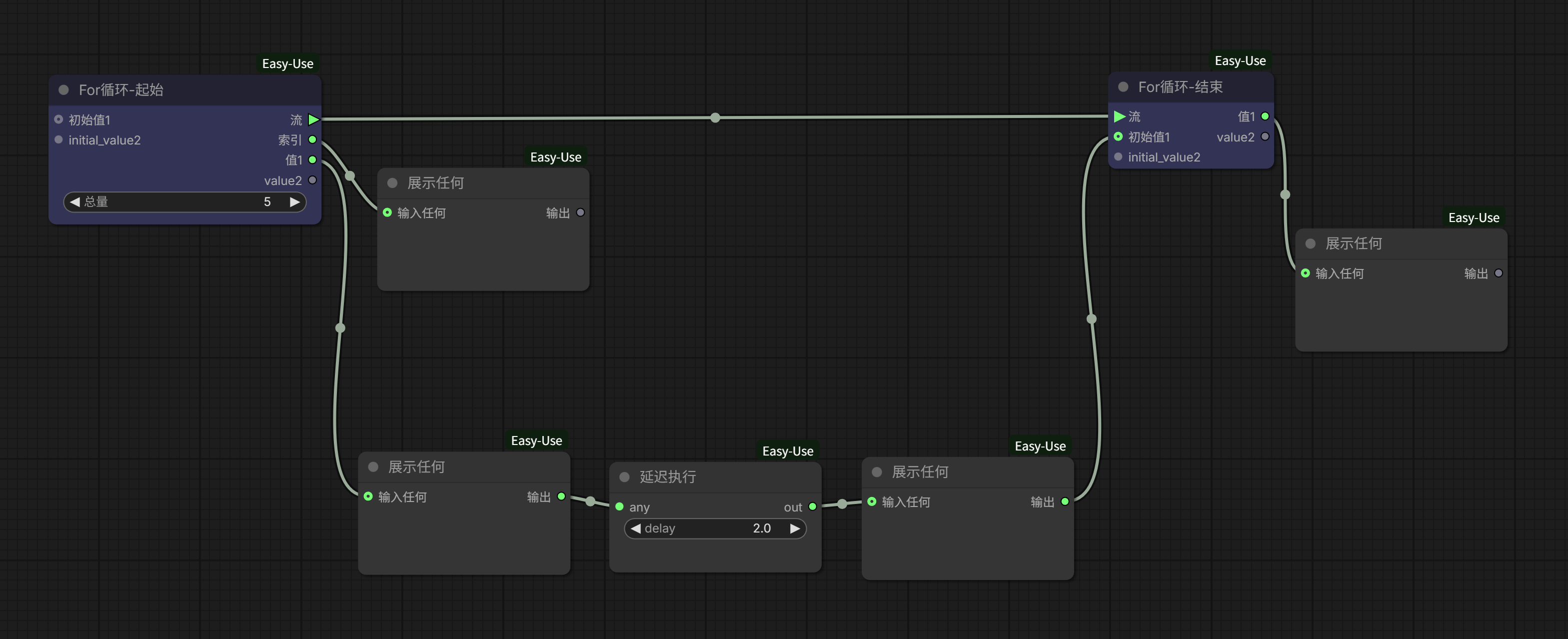
Set the total to 5 times and run.
From the execution, you can observe:
- The value of “index” starts from 0 and automatically increments by 1 after each loop completes. The total loop count is 5, so the “index” value goes from 0 to 4.
- Over 5 loops, both “value” and “initial value” are null (empty). Meanwhile, the “value” output on the right side of the end node only displays null after the entire workflow finishes running.
Next, keeping the display and delay nodes, let’s build another workflow that connects from the index to the end node, like this:
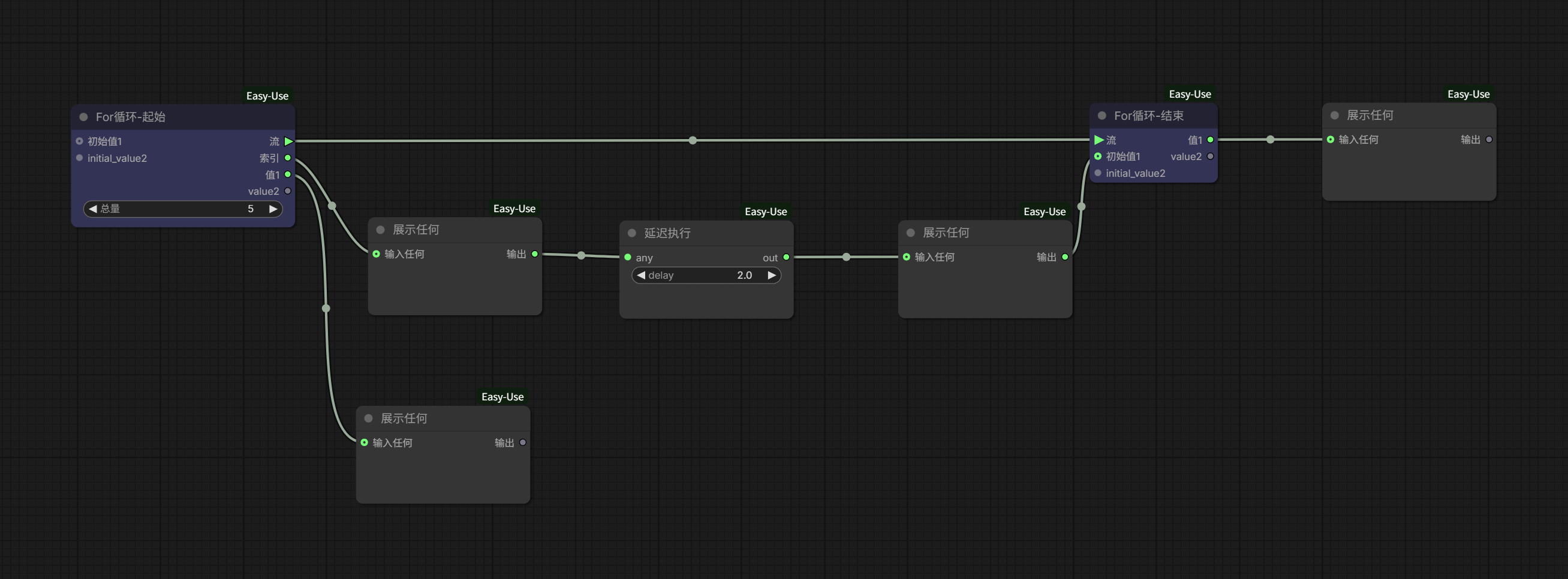
Again, run it 5 times.
This time, you can observe:
- The “index” value still starts from 0 and automatically increments by 1 after each loop completes. The total loop count is 5, so the “index” value goes from 0 to 4.
- The “initial value” on the end node changes with the index. After the entire workflow finishes, the “value” output on the right side of the end node shows the last index value, 4.
- The start node’s “value” is initially null, but from the second loop onwards, it is automatically assigned the “index” value from the previous loop, which is the end node’s “initial value” in the same loop iteration.
Comparing the two, we can now understand the “index” item. It indexes the loop count, but the index value starts from 0. The index value for the first loop is 0, for the second loop it’s 1, and so on.
Also, you can learn a small fact: The “value” on the right endpoint of the For Loop end node only outputs after the entire loop ends; and the start node’s “value” seems to change with the end node’s “initial value”.
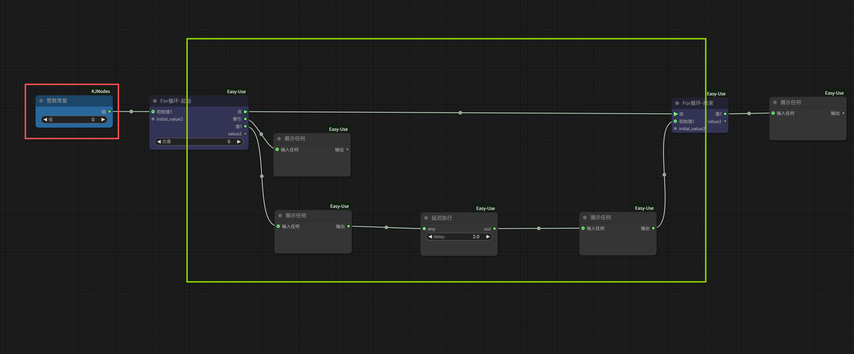
Let’s continue with the same workflow. We’ll add an “Integer Constant” node on the left, connect it to the initial value, and assign an initial value to it.
According to ComfyUI’s basic logic, the start node “Integer Constant” will only execute once. Combined with the previous knowledge, the end node’s output also only outputs once at the end. Therefore, the part that actually participates in the loop is the green-boxed area in the image below; anything outside the green box does not participate in the loop.
Run it once with the initial value set to 0, and again with it set to 3.
When the assigned initial value is 0, the subsequent value remains 0; when the assigned initial value is 3, the subsequent value remains 3.
So now, regarding the start node, we can draw a conclusion:
When the workflow starts running, if no initial value is assigned to the start node’s initial value, then the value output here is null (empty); if we assign an initial value in advance, then the value output is the initial value.
Then, what is the end node’s initial value?
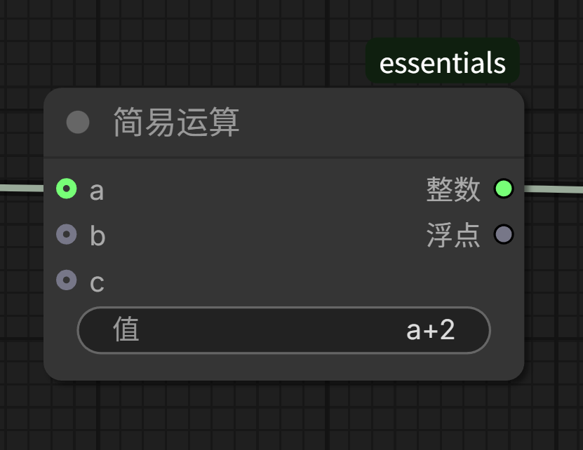
We’ll insert a “Simple Math” node into the previous workflow.
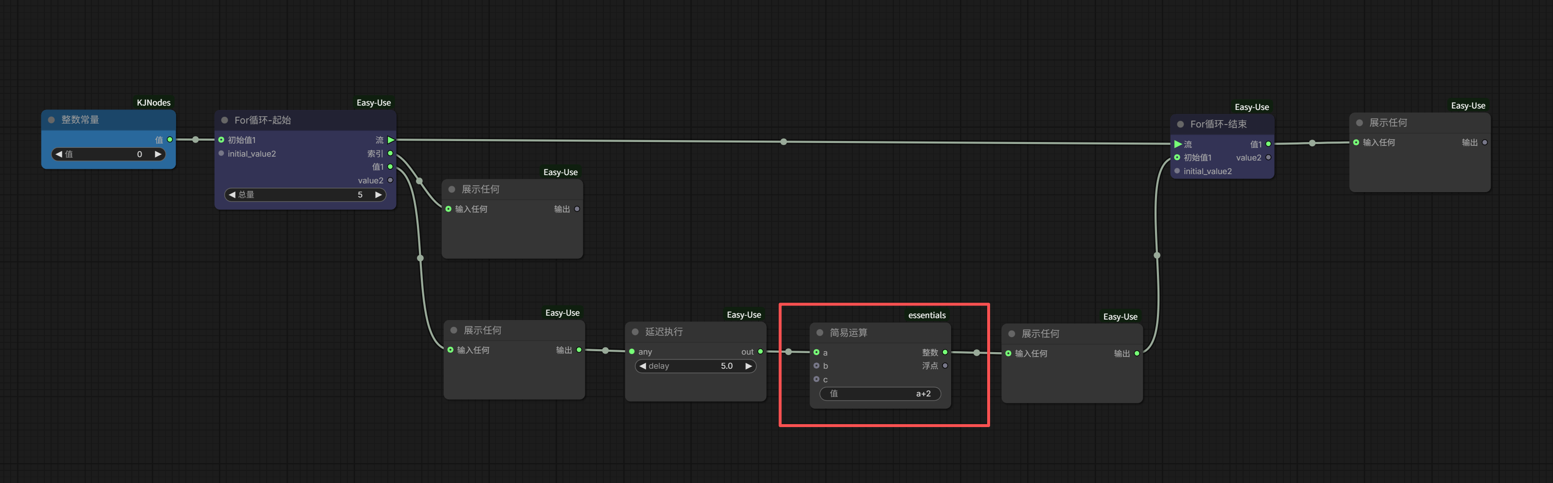
A brief explanation: This node assigns the value passed from the front to ‘a’, then performs the operation a+2, and outputs it to the subsequent node.
Execute it.
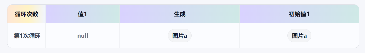
I used a simple table to record the execution results:
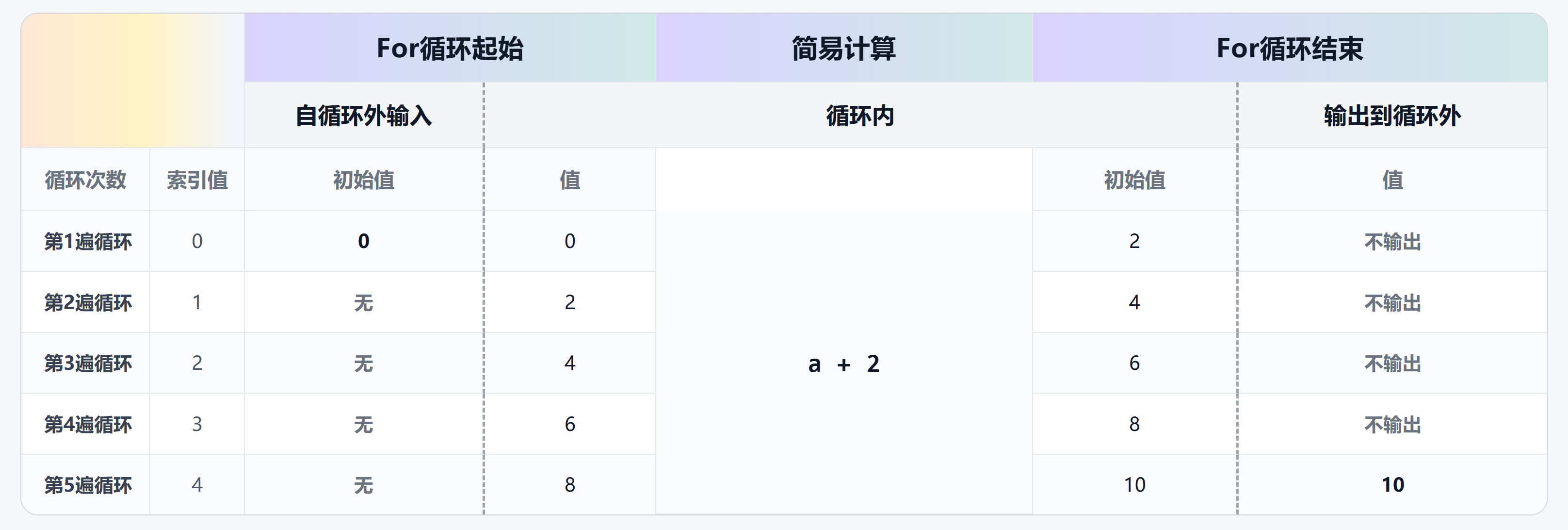
The end node’s “initial value” is indeed the “value” that participates in the next loop iteration, which can also be said to be equivalent to the start node’s “initial value” for the next iteration.
Now remove the redundant display and wait nodes from the workflow.
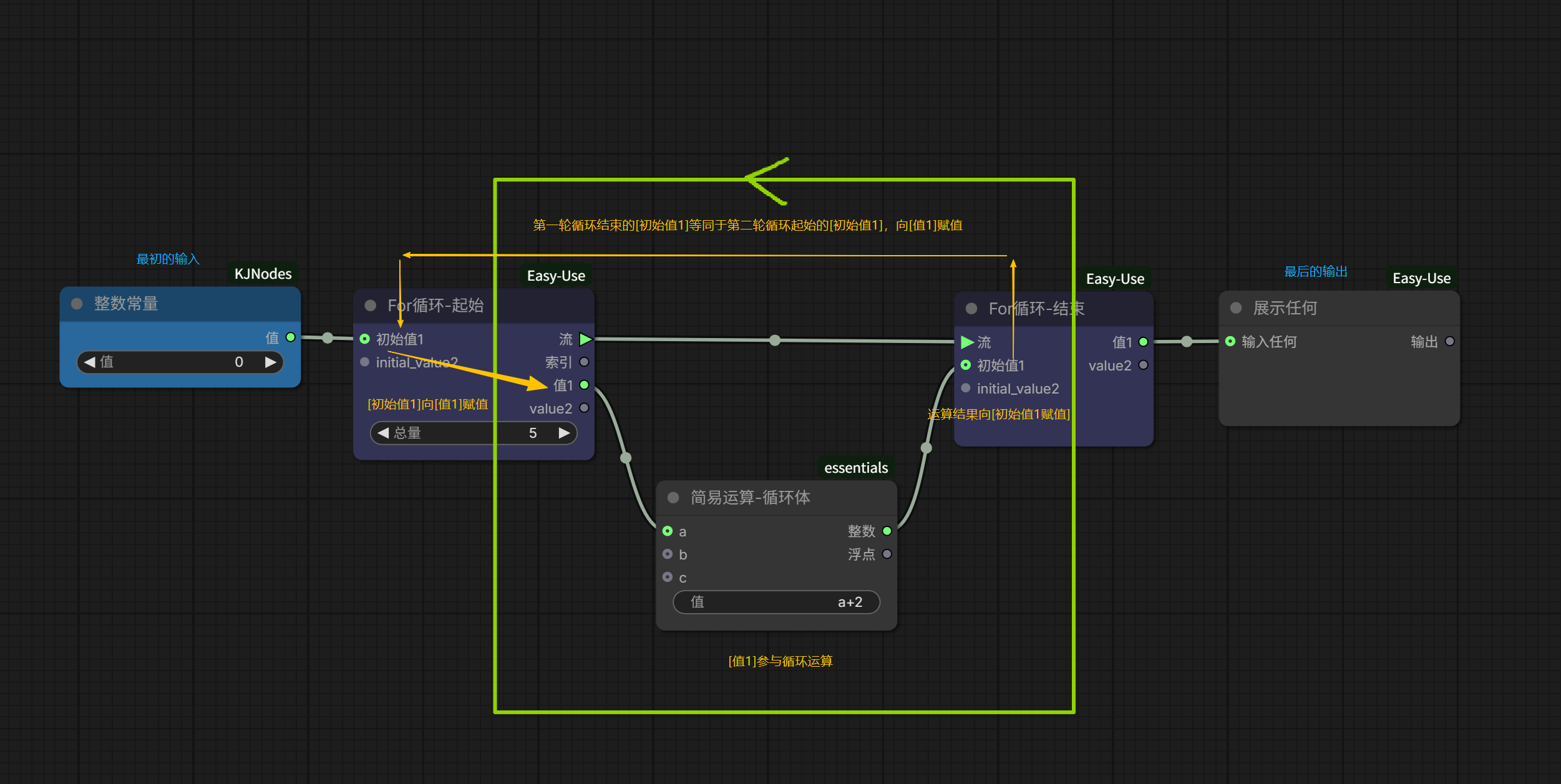
The assignment logic behind this loop is very clear now:
- If an initial value is input, the start node uses this value to participate in the first loop; otherwise, it participates with a null value;
- The result of the first loop serves as the initial value for the second loop, and so on;
- Until the set number of loops (total) is completed, the end node outputs the final result.
If there are also initial_value2/value2, the same logic applies; the two lines run in parallel, each performing its own loop.
Now, all 5 basic items are clear, and the flow logic of the loop should have no issues.
We’ve now understood the basic operational logic of the For Loop, but just knowing the principle isn’t enough. A new question immediately arises: How to apply it?
We build loops in ComfyUI not to have it idle back and forth between start and end, nor simply for numerical operations. Our goal is to achieve batch generation/processing of images and videos through the For Loop.
So, how do we make a process that needs to repeat actually loop?
The answer is: Find a way to connect it into this circle, allowing the start node’s output to “flow through” the process you want to loop, and finally merge into the end node.

At first glance, it seems simple—like drawing a circuit diagram and connecting components, just plug in the part that needs to loop.
But when you actually start building it, problems arise.
As shown in the image below, the blue grouped section is a very basic SD1.5 image generation workflow:
Whether it’s the Checkpoint Loader, the CLIP Text Encoder, or the Latent, there seems to be no place to connect to the For Loop’s start node. There’s no way to connect it, so what do we do?
That’s why I said in the previous article that Prompt Line is a very convenient shortcut node. It has a built-in loop, so we don’t need to consider how to trigger the loop at all. But when writing a For loop ourselves, we still need to consider this issue.
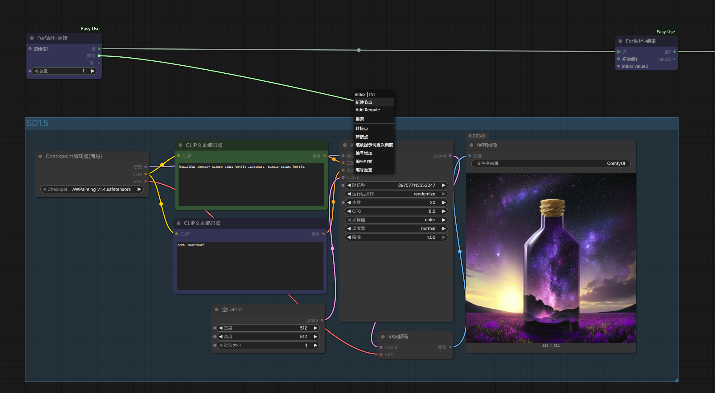
I won’t beat around the bush; the answer is that usually, the method you can adopt is: numerical connection.
The process we want to repeat is an image generation process, so the final displayed value must include an image to view the generated result. We connect a “Preview Image” to the rightmost “value1” output. This image should come from the output of the SD1.5 generation process, so we connect the “image” from the “VAE Decode” below to “initial value1”.
Now, the loop circle and the part that needs to be looped still haven’t established a true closed-loop connection.
How to connect? We see that the start node still has two ports that can output externally: “index” and “value1”. However, “value1” is actually not usable because during the loop, “value1” will be assigned by “initial value1”, so its value type must be an image, not a number. But “index” itself will automatically output incrementing numbers like 0, 1, 2… and since we’re looping image generation, we definitely need to output different images. This number should change with the loop count, so choosing “index” is perfect.
Looking at the SD1.5 generation process below, which number is allowed to change without affecting the stability and quality of the image generation? It’s not hard to find: “random seed”. We connect the index to the random seed.
Now we’ve successfully closed the loop. Click run, and it loops to generate 5 images:
Loop successfully implemented.
However, if you’re observant, you might notice two small issues.
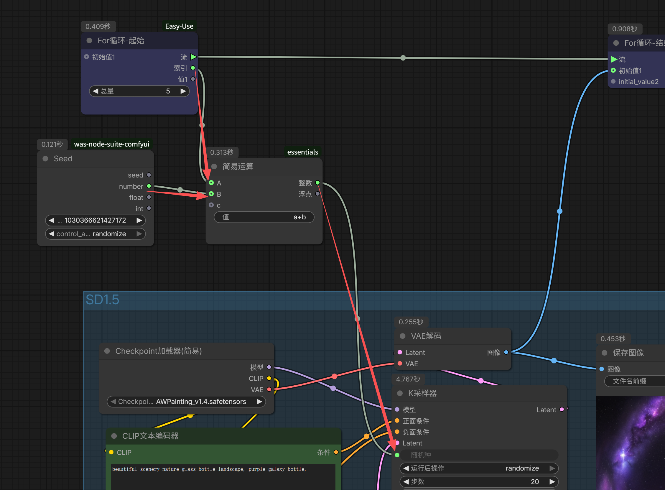
The first issue: If you directly connect the index to the random seed, the image generation seed will increment sequentially from 0, 1, 2, 3…, making it completely non-random.
But we can fix this with a simple formula calculation.
Create a new Random Seed node to generate a random seed; then create a new Simple Math node, assign the index to ‘a’, assign the random seed value to ‘b’, compute their sum a+b, and then assign the sum a+b to the KSampler’s random seed in the generation process. This restores the randomness.
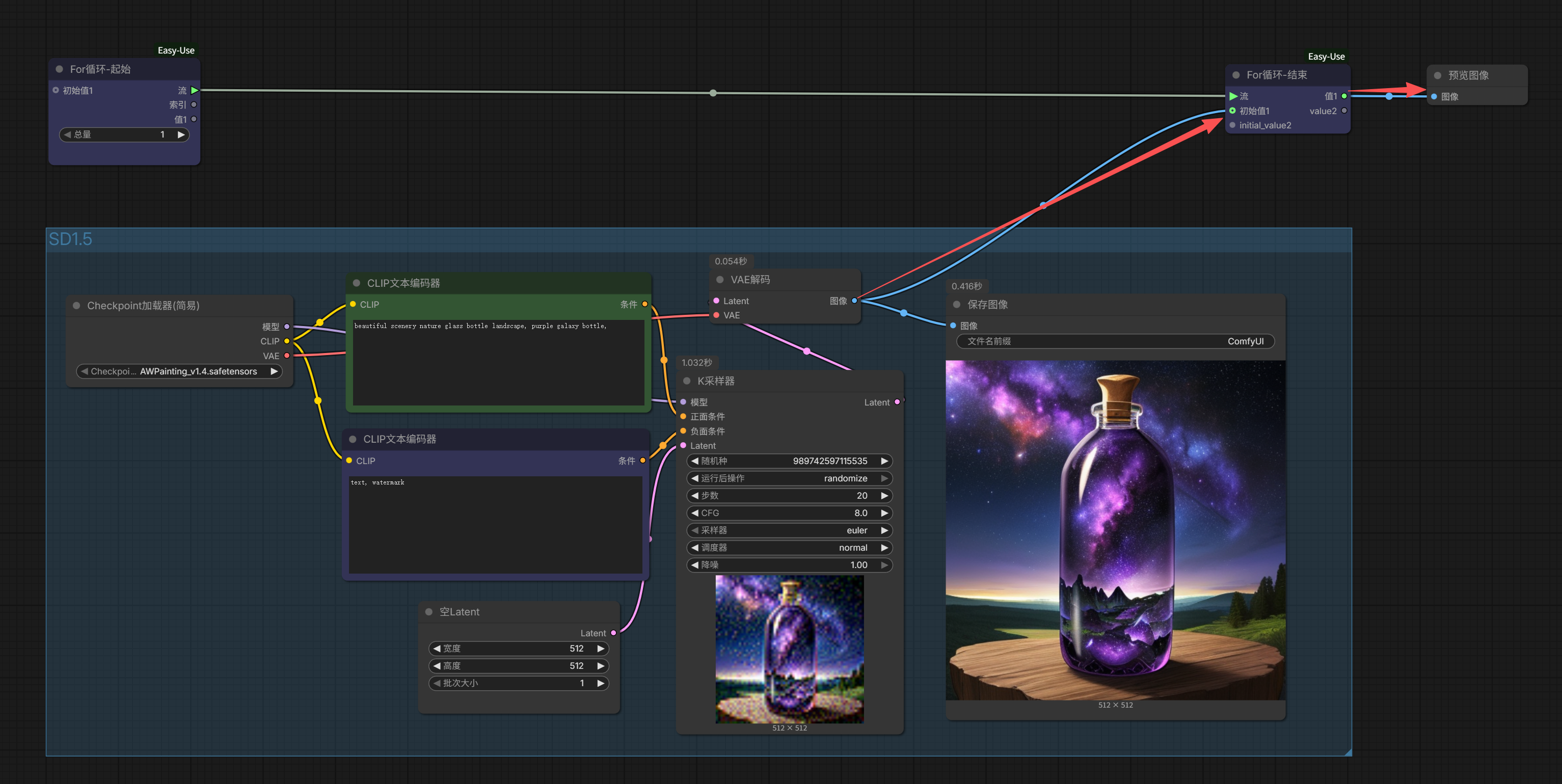
The other issue: The preview image can now only output the result of the last loop iteration, making it impossible to quickly view all the generated images from the batch, which is very inconvenient.
To solve this problem, we need to use a new node: “Any Batch Combine”.
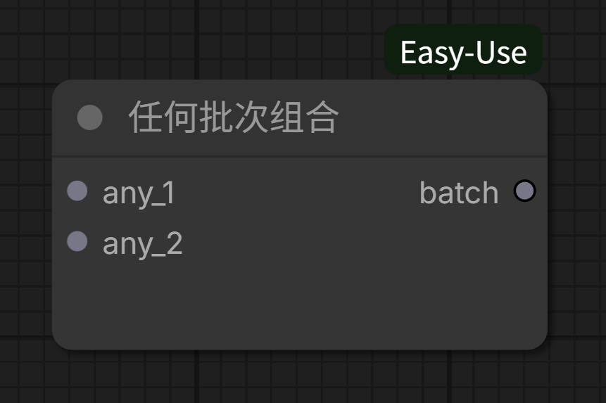
Its function is to combine any_1 and any_2; we’ll explain in detail later.
The connection method is simple: Place it in series between the looped process and the end node’s initial value1 (or other number) input. Then, connect the other input node to the For Loop’s value1 (or other corresponding number):
Let’s first recall the For Loop assignment logic mentioned earlier.
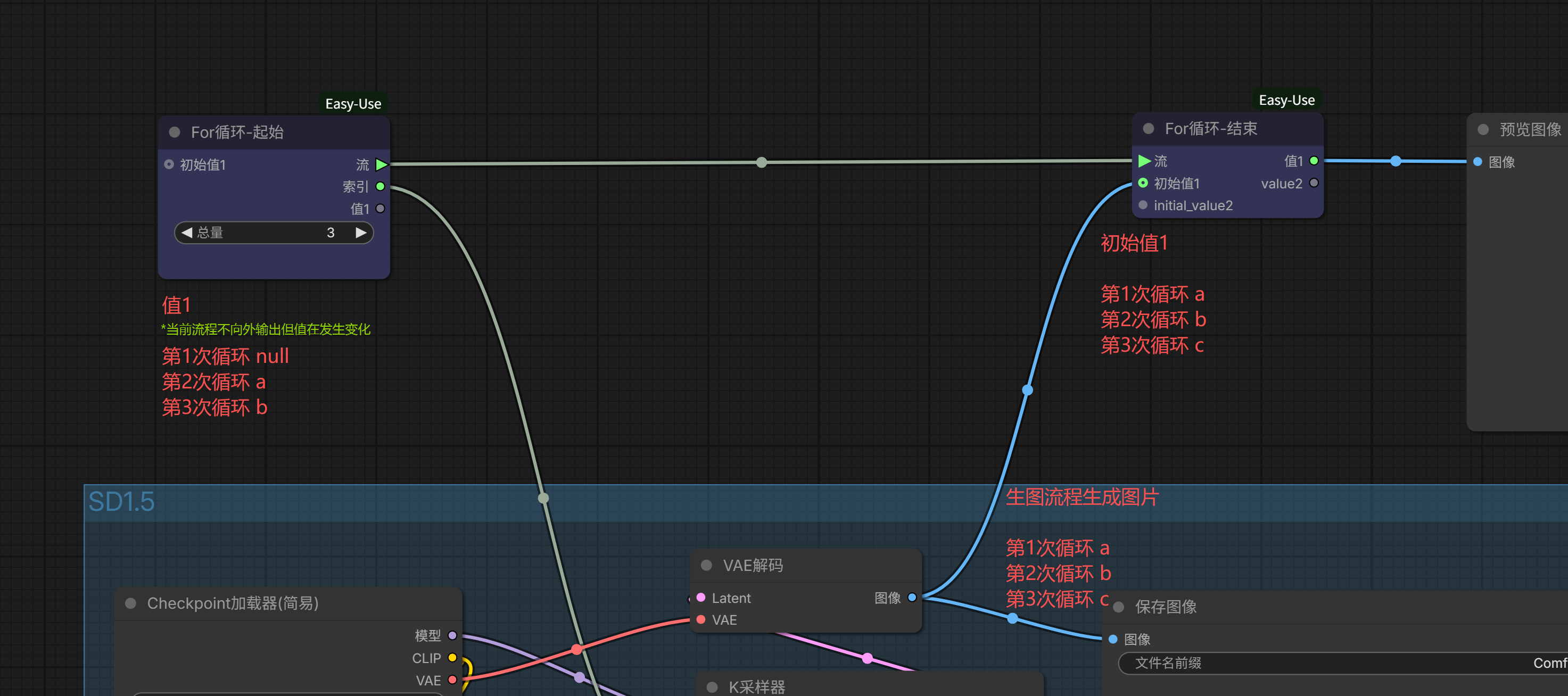
Assuming the image generated in the first loop is ‘a’. Since the image output is connected to (the end node’s) initial value1, initial value1 is also assigned image ‘a’;
In the second loop, although in this workflow (the start node’s) value1 doesn’t output to the next stage, it still changes on its own. Because initial value1 was image ‘a’ in the previous loop, this loop’s value1 is assigned image ‘a’. It enters the generation process below, generating image ‘b’. Similarly, initial value1 also becomes image ‘b’.

Continuing to the third loop, similarly, value1 becomes initial value1’s image ‘b’, generates image ‘c’, and initial value1 becomes image ‘c’.

Finally, the loop ends, and value1 outputs image ‘c’.
Notice the problem? Initial value1 is overwritten each time, so what’s output after the loop ends is only the last result.
“Any Batch Combine” solves this overwriting problem.
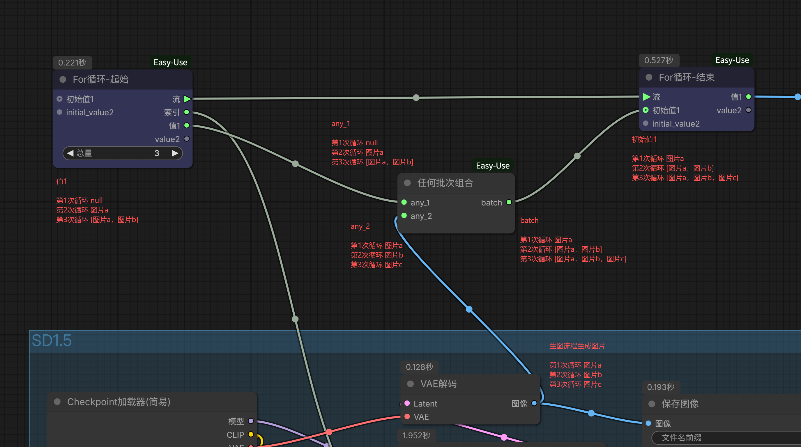
It utilizes the (start node’s) value1 that doesn’t output to the next stage, temporarily storing the previous loop’s initial value1, then merging it with the current loop’s generated result and assigning it to the current loop’s initial value1.
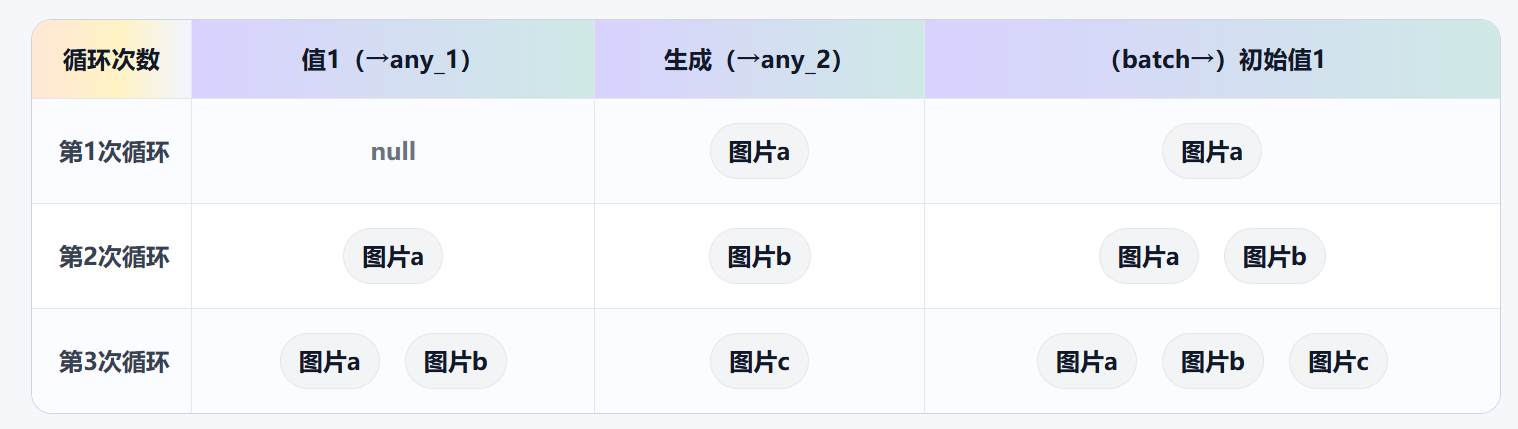
When the loop ends, value1 outputs the last initial value1, which is [image ‘a’, image ‘b’, image ‘c’].
At this point, you’ve mastered the basic application method of the For Loop.
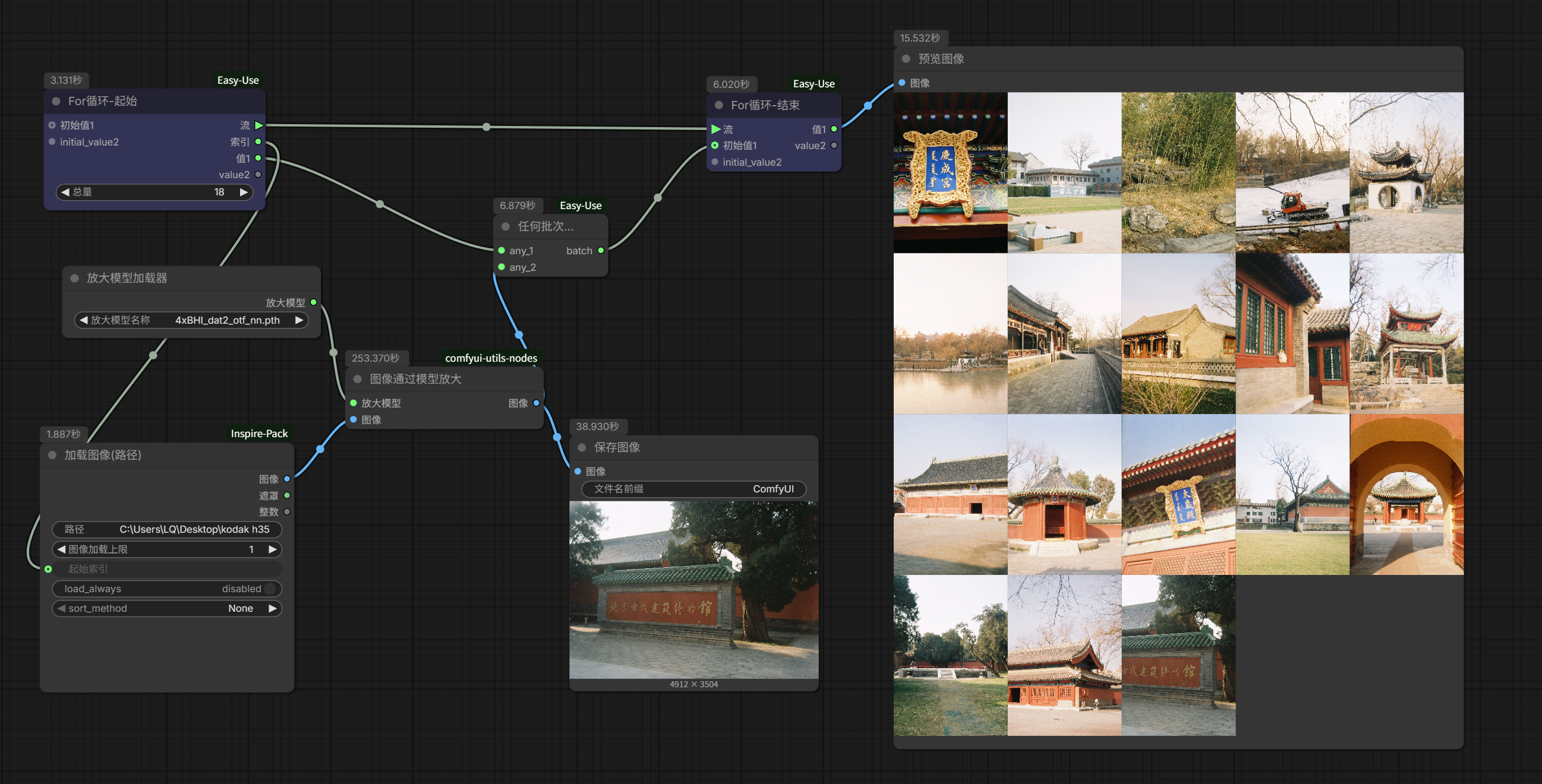
The previous article mentioned that besides multi-prompt image generation, using the For Loop can also achieve batch processing of files and images. For example, batch upscaling.
I happen to have some photos scanned from a Kodak EKTAR H35 half-frame film camera. After cropping to single frames, they’re less than 1300×900, with a pitiful just over 1 megapixel by pixel count. We can use them for a demonstration.
For upscaling real photos specifically, I’ve always highly recommended a series of upscaling models published by Philip Hofmann (https://github.com/Phhofm/models). I previously wrote an article introducing one of them: ComfyUI | How to upscale photos with AI without blurring? Recommending an obscure image upscaling model. These models generally don’t involve significant repainting, so they can avoid some negative modifications caused by AI editing. For example, in a previous article, we used the Qwen edit model to process the dome of the Temple of Heaven. At that time, the tile lines and textures underwent strange distortions, which wouldn’t happen when using these upscaling models.
This time, I chose to use Philip Hofmann’s upscaling model 4xBHI_dat2_otf_nn. It performs 4x high-definition upscaling without excessive noise reduction. Even when upscaling from 11 megapixels to 180 megapixels, at 100% zoom view, there are still certain details, and the film’s grain texture is well preserved.

Since there is no repainting involved, the workflow is also very simple:

Now, start thinking: How should we design the loop so that this process can batch automatically process images in a folder?
First, we need a node that can load images from a folder path. It’s best if it has an index function, enabling one-by-one loading. There are actually quite a few such loading nodes, like those typically included in integration packs, such as Inspire-Pack and KJNodes.
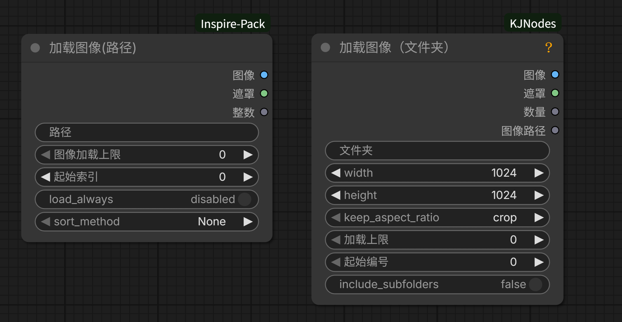
I generally prefer to use this “Load Image (Path)”.
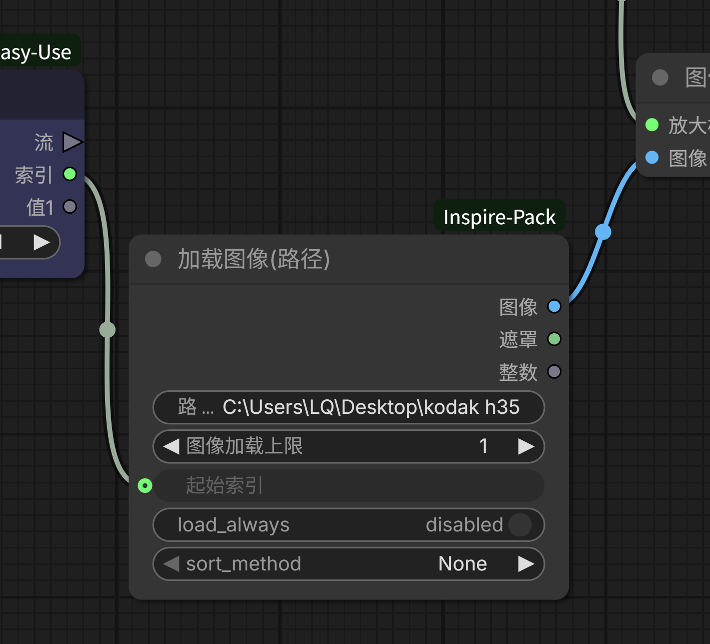
Use it to replace the original single image loading node, then connect the loop start node’s index to the start index. This way, it can automatically load in order from 0, 1, 2, 3… Since we need to upscale each image individually, set the image load limit to 1, meaning it loads 1 image each time.
Set the loop count to match the number of images in the folder, and add an “Any Batch Combine” node to allow previewing all upscaled images at once after the loop ends.
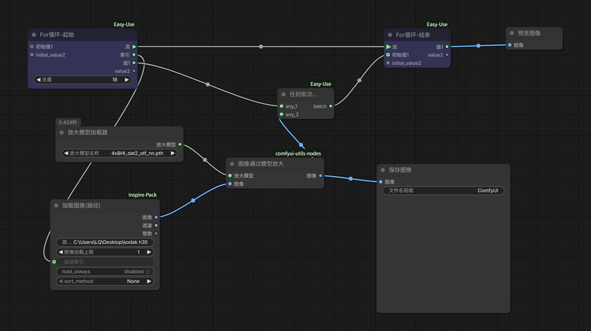
It’s that simple.
Of course, you can also do some other variations. For example, recently Comfy official updated a batch of image editing templates. A few of them I find quite interesting, like this one:
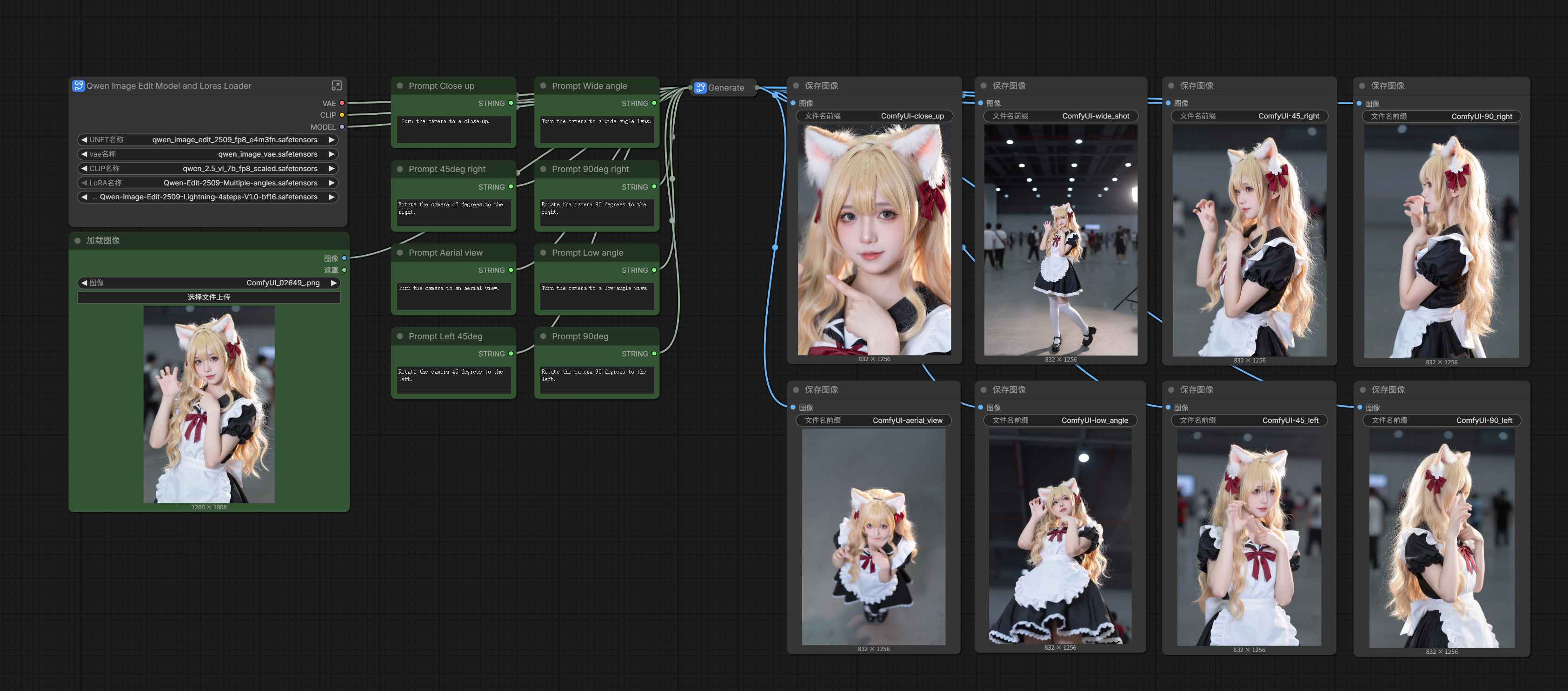
Based on the Qwen-Image-Edit model, upload one image, and you can get perspectives from 8 angles.
I particularly like the top-down perspective, somewhat like a low-altitude drone angle, very interesting.
So I can slightly adjust this workflow, add a For Loop, and batch generate top-down perspective new images for an entire set of images; meanwhile, I can connect the original image loading to the value2 loop, so that the original can be compared with the generated results:
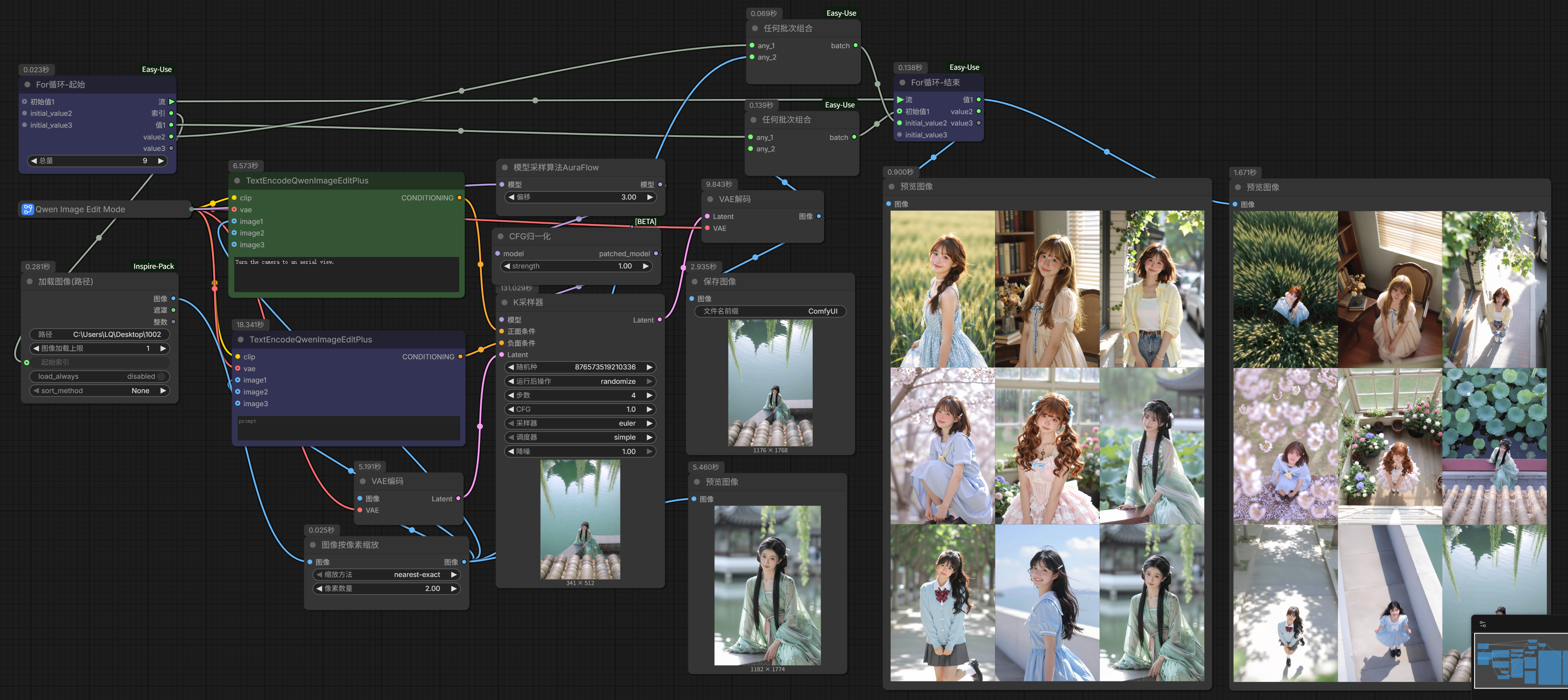
The perspective transformation in this workflow is based on prompts. If you wish, you can also nest another prompt loop to output any perspective you want for each image (cough, mind the decency) or perform fixed element additions, deletions, and modifications on the image content to achieve multiple outputs.
The For Loop can be combined with different nodes for different play styles. For example, as mentioned in the previous article, using LLM to generate multiple prompts, adding a For Loop combined with Excel read/write nodes, leaving great room for both reverse engineering and editing; for example, combining with intelligent segmentation nodes like SAM, you can achieve batch image cutout editing, watermark removal, and other functions; for example, combining with some image processing and logic nodes, you can achieve automatic image splitting and merging, one-click color grading, and more…
Mastering the basic logic and application of the For Loop opens up all these possibilities for you to freely explore.